What are Harmonics?Modern low voltage networks increasingly have loads installed that draw non –sinusoidal currents from the power distribution system. These load currents case voltage drops through the system impedances, which distort the original sinusoidal supply voltage. Fourier analysis can be used to separate these superimposed waveforms into the basic oscillation (supply frequency) and the individual harmonics. The frequencies of the harmonics are integral multiples of the basic oscillation and are denoted by the ordinal number ”n” or ”v” (Example: supply frequency = 50Hz then 5th Harmonic = 250Hz). src="http://pagead2.googlesyndication.com/pagead/show_ads.js">
Linear Loads:- Ohmic resistances (resistance heaters, light bulbs, etc.,)
Non – linear loads (harmonic generators) :- Transformers and chokes
- Electronic power converters
- Rectifiers and converters, especially when controlling variable-speed induction
- Motors
- Induction and electric arc furnaces, welding equipment
- Uninterruptible power supplies (UPS Systems)
- Single – phase switch mode power supply units for modern electronic loads such as televisions, VCRs, computers, monitors, printers, telefax machines, ballasts,
- Compact energy saving lamps
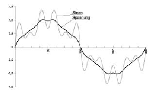
Figure - 6
 Network current and voltage superimposed with the following harmonics :5% of the 5th Harmonic,4% of the 7th Harmonic and2.5% of the 11th HarmonicHarmonics are produced not only in industrial networks but also increasingly in private households. As a rule, those loads that draw non – sinusoidal current only give rise to odd harmonics i.e. it is mainly the 3rd, 5th, 7th, 9th, 11th etc. harmonics that are present.How are harmonics produced?In a commercial facility’s own low – voltage network, especially when variable speed drives are installed. In every households: in every television, computer and in compact energy – saving lamps with electronic ballasts. The sheer number of these loads in the evenings with the currents in phase give rise to high levels of harmonics in some medium – voltage networks.
Figure - 7
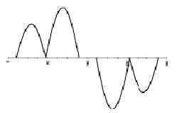
Figure -8

What is the level of harmonics if no PFC system has not yet been installed?
a. In a facility’s own low voltage system:
Depending on the power of the installed converters and rectifiers.If, for example, a large six – pulse converter is installed in the network and its powerrating is 50% of the transformer nominal rating, this gives rise to about- 4% of the 5th harmonic (250Hz) and
- 3% of the 7th harmonic (350Hz)
It is more usual however, for several small converters that are not linked to each other to be installed in a network. The fact that the currents to the individual rectifiers are not all in phase means that the resulting harmonics voltages are less than in the above case. If, for example, several rectifiers with a combined power of some 25% of the transformernominal rating are installed, this gives rise to some- 1 – 1.5 % of the 5th harmonic and
- 0.7 – 1% of the 7th harmonic.
These are approximate values to help in the initial assessment of whether choked power
factor correction system needs to be installed.
b) In the medium – voltage supply system:
Nowadays, most of these systems are affected predominantly by the apparatus in private households (mainly television sets) that produce harmonics. This is readily apparent when the daily curve for the 5th harmonic is examined:
Figure - 9
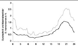 The level of harmonics in the medium – voltage system of a municipal power supply withIndustrial loads on weekdays.Average and maximum levels in a series of measurements carried out in 1985-1987 by the FGH electrical industry’s research association, in Mannheim. It can be assumed with certainty that these levels are even higher today. The peak in the evenings is caused by the large number of television sets and other non – linear loads in private households.In densely populated areas in the evenings, frequencies of about 4% 250Hz and up to 1.5% 350Hz can be superimposed on the medium – voltage supply system. The higher harmonics are usually negligible. Predictions of harmonics have only a limited accuracy.What must be done if the harmonic factor is high, but the reactive power demandis small?Basically there are several solutions to limit harmonic currents caused by the use of loads that inevitably generate them.Well – known measures to solve the problem include the use of
- several passive filters tuned to work together (tuned acceptor circuits) or
- assembling highly non-linear loads and sensitive consumers into separate groups, feeding each group by means of a separate transformer
However, these solutions involve two main disadvantages:- Improvement of the system disturbance characteristics applies to the particular installation involved. Each subsequent extension can mean that the initial investment becomes worthless.
- It is often very difficult to implement these solutions in practice for an existing installation.
Excessively high harmonics levels often occur due to the use of unchoked capacitors innetworks that are distorted by harmonics.Today, the most cost – effective solution for these problems is still the use of heavy dutyfilter circuit sytems.For problems with ;- Excessively high levels of 3rd, 9th and 15th harmonics and the high neutral conductor current they give rise to, or
- the demand for tuned acceptor circuits to maintain the harmonic current returned to the medium – voltage system under a specified limit or
- low demand for reactive power but high harmonic currents, for example, due to a large proportion of converter – controlled induction motors.
The OSF active filter or a combination of a filter circuit system with an active
filter is the optimum solution.
The decisive advantage of ac active harmonic filter lies in the fact that the correction of network disturbances still remains effective if subsequent extensions are made to the installation. The flexibility of the active filter means that the required nominal size can be selected quite simply from the current demand. Any additional demand due to extensions of the installation can be met at any time by adding further components.
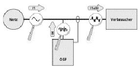
Operating Principle of the active filter
Figure - 10
 I1 = Fundamental Current
IH = Harmonic Current
The active filter is installed in parallel to the harmonic generators. It analyses the harmonic current produced by the non linear loads and supplies a 180° out – of – phase compensating current, either over the entire spectrum from the 2nd to the 25th harmonic or a specially selected harmonic. This action neutralizes the corresponding harmonic currents completely at the point of connection, provided that the system has been appropriately dimensioned.
The combination of harmonic filter and harmonic load appears to the network as an overall linear load drawing a sinusoidal current. Installation is quite simple. A threephase feeder with or without a neutral conductor needs to be available. The Current transformer is then installed in the line to the non – linear load.
Figure - 11
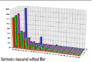
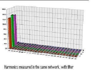
Figure - 12
 ApplicationsTypical applications are in :
- Low voltage systems with many converters that are under an obligation to return only limited harmonic currents to the preceding network, where, for example, longspur lines to remote installations are involved.
- Modern converter drives that return high levels of harmonics to the distribution system, but with only a low demand for reactive power. In a low – Voltage network with a 1000KVA transformer and many small induction motors in use, it is possible that a power factor correction system rated at 400 KVAR is necessary. When modern converters are used, the demand still amounts to some 100kVAr.
- Low - Voltage systems with a large proportion of the third harmonic due to the use of single-phase loads. These low voltage networks display an extraordinarily high current in the neutral conductor, which should be approximately 0A when the load is disturbed almost symmetrically. Because of the electronic loads, however the harmonic currents in the three phases are added together in the neutral conductor in addition to any imbalance in the ohmic loads. This is because the 3rd, 9th and 15th harmonics in the three phases have the same phase angle. The result is a current in the neutral conductor, which, under certain conditions, can be greater than the phase current and overloads the neutral conductor, which has not been dimensioned for loads of that magnitude.

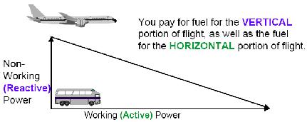

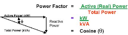

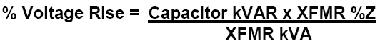
 3. Voltage Improvement: